Building the Lunch Tray Drone

Joined
Oct 21, 2023
Messages
98
Reaction score
55
Age
75
P3P Build

To start with I did not crash this P3P, (Phantom 3 Pro). I purchased several P3P’s in an attempt to get a good working drone. Well, I got several good working P3P’s and one all messed up P3P. The top and bottom shells were cracked, thread holes were stripped, drone was painted, camera motor and bearings were locked up.

OK so here I have P3P that does power up and the motors do run, but I would not want to fly it. So, I thought why not put all the good parts in a new shell or frame. The following build is what I came up with, the Lunch Tray Drone.

As I go through this build you will notice that my sentence structure may not be grammar perfect. I am from a Pennsylvania Dutch background so that is my excuse.

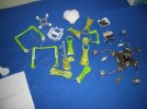
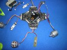
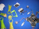
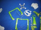
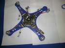
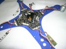
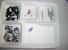
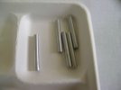
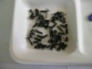
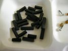
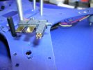
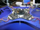
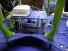
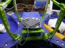
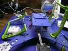
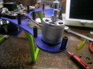
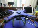
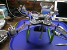
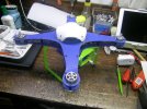
I started by taking this drone completely apart, and laid it out to see that I had to work with. With the complete shell removed I had everything I needed to build a “flat frame” drone. In the pictures you will see pieces of the original shell and all the good stuff. I cut the shell up before I thought about taking pictures and showing others what I was doing. The shell was complete but not usable so I throwed it out.

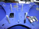
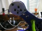
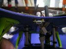
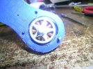
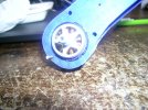
One of the camera gimbal motors was locked or frozen up so I decided to leave the camera off for now. But I made provisions for a future camera under the battery.

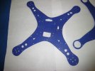
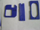
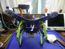
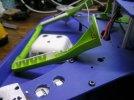
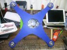
Now I need a frame material, carbon fiber would cost about $50 to $75 to purchase and have shipped to me. Fiberglass is too ridged and does not bend well without cracking. I came up with a sheet of hard plastic but flexible, about .125 inch thick.

Well, I found it on eBay and ordered it. Price was very good so I ordered 4 pieces.

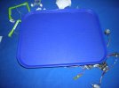
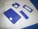
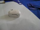
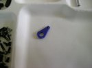
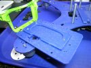
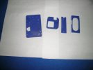
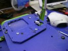
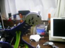
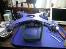
You have to looks hard I should not have taken this picture with a blue back ground.

Now don’t laugh this piece of plastic will work great. Yes, it is a cafetería lunch tray. The material is hard but flexible, when you drill and tap threads in this material it works great.

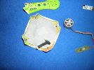
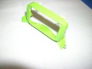
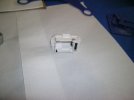
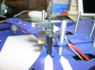
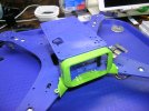
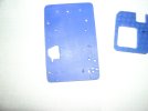
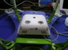
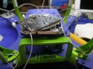
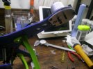
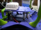
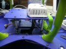
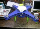
The white “turtle shell” is the remaining part of the top shell. I will be using this to hold the GPS unit.

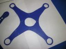
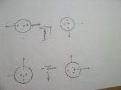
When I disassembled the shells, I traced an outline on graft paper so I could make the new frame the exact size as the P3P.

More later.
 

Attachments

  • DSCN9458.JPG
    DSCN9458.JPG
    859.3 KB · Views: 54
  • DSCN9462.JPG
    DSCN9462.JPG
    771 KB · Views: 52
  • DSCN9457.JPG
    DSCN9457.JPG
    483 KB · Views: 50
  • DSCN9463.JPG
    DSCN9463.JPG
    1,012.9 KB · Views: 55
  • DSCN9461.JPG
    DSCN9461.JPG
    1.1 MB · Views: 56
  • DSCN9460.JPG
    DSCN9460.JPG
    955.6 KB · Views: 55
  • DSCN9459.JPG
    DSCN9459.JPG
    877.8 KB · Views: 54
Yea I got plenty of time. I am retired, it is between 0 and 20 degrees outside with 10 to 40 mph winds. Snowed everyday for about 3 weeks now. I live in the mountains of Potter County Pa. So I got plenty of time to watch the deer out my windows or work on and read about these DJI drones. Or, I can watch TV or argue with the wife and I can't win with either of those.
Keep watch this post, it gets better.
 
  • Like
Reactions: brigerdrones
Post 2

I took the graph paper cut out of the p3p and cut out two drone plates. One will be for the bottom and the other will be the top plate. The bottom plate is the most labor intensive of the two. I used my original tracing of the bottom shell to get my motor-to-motor center lines and distance between motors.

This bottom plate has 101 holes drilled or cut into it, and that is an actual number. Next, I laid the top plate on the bottom plate marked and drilled the center holes for each motor and the 24 plate separators stand-offs. The stand-offs will act as the frame struts. Next, I needed to know how much distance I needed between the top and bottom plate.

I laid the main board and motors on the bottom plate and came up with 3/16 of an inch. I cut 4 small rubber tube spacers and installed them under the main board. I added rubber washers (to help with vibration) on the top of the main board and installed #4 screws through the main board and into the bottom plate. While I was doing this, I found 4 motor wires that were pinched between the upper and lower shells by the last owner, I guess. The wires were all but cut clean through. I repaired them.

The stand-offs are made from black nylon hex style with M3 x 0.5 threads tapped completely through the stand-off. The stand-offs closest to the motors are .593 of an inch, the stand-offs in the middle of each arm are .800 of an inch and the center stand-offs are .910 of an inch. Holes in the plates for the stand-offs are .125 of an inch for the M3 screws. The screws are metal Torx drive button head M3 x 0.5.

These stand-offs make the flexible plates ridged but not as solid as a fiberglass plate.

Next, I had to come up with a way to use the battery entrance collar (green color part in pics) that also holds the battery in the drone with a click snap. I mounted the collar with two screws on to the edge of the bottom plate. Now I made a small plate to hold the battery, it is attached to the battery collar. 5 aluminum stand-offs were mounted between the bottom of the bottom plate and the top of the small plate under the battery. This made a very strong and secure battery holder. I mounted the power connector for the battery to a stand-off on the top of the small plate. I used a scrapped battery head with the power connections in it to help place the connector. I added a jumper tab (blue) between the aluminum stand-off and the power connector. There is also a small boss that extends up into the bottom of the bottom plate. This gives me a very solid connector for the battery to snap into. 4 small connectors in this power connector are spring loaded and the connector must be mounted solid.

With all that done I had too much space above and below the battery. I made two small plastic pieces and mounted one above the battery and one below.

Now the plate under the battery will also serve as the mounting plate for FPV and camera mount.

More later.
 

Attachments

  • DSCN9465.JPG
    DSCN9465.JPG
    647.9 KB · Views: 37
  • DSCN9466.JPG
    DSCN9466.JPG
    490.7 KB · Views: 42
  • DSCN9467.JPG
    DSCN9467.JPG
    704.9 KB · Views: 42
  • DSCN9468.JPG
    DSCN9468.JPG
    637.4 KB · Views: 42
  • DSCN9469.JPG
    DSCN9469.JPG
    232.5 KB · Views: 41
  • DSCN9470.JPG
    DSCN9470.JPG
    602.3 KB · Views: 40
  • DSCN9472.JPG
    DSCN9472.JPG
    380.1 KB · Views: 40
  • DSCN9474.JPG
    DSCN9474.JPG
    466.4 KB · Views: 40
  • DSCN9475.JPG
    DSCN9475.JPG
    456.6 KB · Views: 41
  • DSCN9477.JPG
    DSCN9477.JPG
    337.3 KB · Views: 43
Post 2 more pics.

More later.
 

Attachments

  • DSCN9484.JPG
    DSCN9484.JPG
    332.4 KB · Views: 36
  • DSCN9483.JPG
    DSCN9483.JPG
    423.4 KB · Views: 35
  • DSCN9482.JPG
    DSCN9482.JPG
    355.4 KB · Views: 34
  • DSCN9481.JPG
    DSCN9481.JPG
    350.2 KB · Views: 40
  • Like
Reactions: Harleydude
I have a question, if there are any "moderators" reading this post, would it be possible to change the title to LTP3P?
(Lunch Tray Phantom 3 Pro). It sounds better then Lunch Tray Drone.
 
Post #3
4 small plates are cut out for the battery holder.
Next move, mount the aluminum stand-offs to the top of the bottom plate. Next add battery top spacer.
Mount battery collar (green) edge of rear of the bottom plate. Now all the screws are in the bottom plate that will be covered by the main board, so we can mount the main board on the top side of the bottom plate. You must use a very thin (#4) screw. I used spacers under the board for clearance and rubber washers on top of the board. See white arrows.
Mount power connector to the black nylon stand-off and the blue tab attached to the aluminum stand-off. See white arrows.
Add battery bottom plate to the green battery collar and screw it down to the edge of the rear of the bottom plate.
 

Attachments

  • DSCN9497.JPG
    DSCN9497.JPG
    590.2 KB · Views: 31
  • DSCN9495.JPG
    DSCN9495.JPG
    947.6 KB · Views: 32
  • DSCN9494.JPG
    DSCN9494.JPG
    641.8 KB · Views: 34
  • DSCN9493.JPG
    DSCN9493.JPG
    751.3 KB · Views: 32
  • DSCN9492.JPG
    DSCN9492.JPG
    703.5 KB · Views: 30
  • DSCN9491.JPG
    DSCN9491.JPG
    657.3 KB · Views: 32
  • DSCN9490.JPG
    DSCN9490.JPG
    818.5 KB · Views: 30
  • DSCN9489.JPG
    DSCN9489.JPG
    508.9 KB · Views: 31
  • DSCN9487.JPG
    DSCN9487.JPG
    344.8 KB · Views: 29
  • DSCN9485.JPG
    DSCN9485.JPG
    606.9 KB · Views: 30
Post # 4

Next I mounted the landing gear and ran the compass wire up to the main board. Antenna wires are attached to receiver module. module is attached and vision unit is attached to the receiver.
Now we can start mounting the motors. I added .080 aluminum pieces under the plate of each motor, this should help keep the motors in place. I used 2, 3mm studs to line up the aluminum pieces, the plate and the motor shim to the motor mounting holes. I will explain the shims in the next post.
More later.
 

Attachments

  • DSCN9513.JPG
    DSCN9513.JPG
    611.6 KB · Views: 26
  • DSCN9514.JPG
    DSCN9514.JPG
    697.6 KB · Views: 28
  • DSCN9515.JPG
    DSCN9515.JPG
    485.5 KB · Views: 26
  • DSCN9516.JPG
    DSCN9516.JPG
    689.2 KB · Views: 27
  • DSCN9512.JPG
    DSCN9512.JPG
    735 KB · Views: 27
  • DSCN9511.JPG
    DSCN9511.JPG
    687.5 KB · Views: 28
  • DSCN9510.JPG
    DSCN9510.JPG
    655.8 KB · Views: 29
  • DSCN9509.JPG
    DSCN9509.JPG
    645.4 KB · Views: 26
  • DSCN9508.JPG
    DSCN9508.JPG
    650.1 KB · Views: 23
  • DSCN9507.JPG
    DSCN9507.JPG
    766.7 KB · Views: 25
Post # 5

Aircraft and status lights were added, I don't have any lenses for them at this time.
Now if you look at the hand drawn paper picture. You will see the 4 motors with arrows attached to them. #1 motor has an arrow on the left side and the rear of the motor, this means the motor tilts left and back when mounted on the drone. The mounting holes are shown just as DJI mounted them, the 2 narrow spaced holes (16mm) are left and right. The wide spaced holes are forward and rear (19mm) this is on motor #1. If you look at the drawing you can see all 4 motors tilt differently. But the mounting holes for #1 and #3 are the same. #2 and #4 motor mounting holes also match.
I checked 4 different P3P's and all have the same mounting holes and tilt as this drawing.
After hours and hours of measuring motor shaft centers top and bottom and with many many drawings and a protractor I came up with a tilt angle of 4 degrees. This works out to .035 of an inch. This also works for side to side tilt and front to rear tilt.
Now take motor #1, the mounting hole closest to the front and the one on the right are shimmed. This gave the motor the proper tilt. The other two holes get no shims.
Next I had to pre-mount the top plate to check for motor housing clearance between the motor and plate. The motor tilting required the plate holes to be enlarged.
I mounted the mini USB port on the front of the drone.
 

Attachments

  • DSCN9523.JPG
    DSCN9523.JPG
    430.8 KB · Views: 29
  • DSCN9525.JPG
    DSCN9525.JPG
    447.5 KB · Views: 28
  • DSCN9526.JPG
    DSCN9526.JPG
    654.3 KB · Views: 29
  • DSCN9527.JPG
    DSCN9527.JPG
    669.4 KB · Views: 25
  • DSCN9522.JPG
    DSCN9522.JPG
    619.1 KB · Views: 28
  • DSCN9521.JPG
    DSCN9521.JPG
    656 KB · Views: 27
  • DSCN9520.JPG
    DSCN9520.JPG
    672.4 KB · Views: 28
  • DSCN9519.JPG
    DSCN9519.JPG
    762.7 KB · Views: 29
  • DSCN9518.JPG
    DSCN9518.JPG
    729.6 KB · Views: 25
  • DSCN9517.JPG
    DSCN9517.JPG
    817.1 KB · Views: 27
Post # 6

Ok here are some more pictures of the motor to plate clearance. Now the top plate was attached and the drone is taking shape. It is now very rigid and stiff. The hole in the top of the plate is for the GPS mounting. I connected the GPS wire to the main board and mounted the "Turtle Shell" which is the center of the top shell of the original drone.
OK it is done for now, will it start, will it fly?
I will let you know in the next few days.
 

Attachments

  • DSCN9532 (1).JPG
    DSCN9532 (1).JPG
    859.9 KB · Views: 31
  • DSCN9531.JPG
    DSCN9531.JPG
    852.1 KB · Views: 29
  • DSCN9530.JPG
    DSCN9530.JPG
    802.6 KB · Views: 32
  • DSCN9529.JPG
    DSCN9529.JPG
    799.2 KB · Views: 30
  • DSCN9533 (1).JPG
    DSCN9533 (1).JPG
    792.7 KB · Views: 30
OK I got a problem! I connect everything, Ipad to controller, turn on controller and turn on DIJ GO app. All batteries are charged 100%. Turn drone on it beeps like normal and I have solid green lights on the status lights. So compass is calibrated, the controller light is green. I am linked to the drone. I pull down and in on the sticks and nothing, if I do it several times I get an ESC error. I turn the drone off and back on still no motor running. I don't understand the solid green lights. What am I doing wrong?
 
  • Like
Reactions: brigerdrones
I went over everything again I am getting the ESC status error, I restart the drone and same thing comes up, ESC status error!
 
No the DJI GO app shows the IMU is OK should I do the calibration anyway and how do you do it?
 

Recent Posts

Members online

No members online now.

Forum statistics

Threads
143,520
Messages
1,471,098
Members
105,496
Latest member
EstebanP4+